|
Enter into a discussion with any number of woodworkers and chances are it'll invariably move to the router table. In fact, those discussions will cover just everything you ever wanted to know about router tables but were afraid to ask.
What prompted me to write this article? Well, in those discussion circles there will be general chatter about which router - fixed or plunge - works best mounted in the table. There'll also be some banter as to whether or not a vacuum port should be in the router area and perhaps whether or not to buy or build a table. Indeed, it appears that some of us are about as vague on router tables as we are on nuclear physics.
So, in an effort to assist those wishing to build a better router table, I decided that it wouldn't suffice to just write an article about it, but that I had to actually build the table and document the project with pictures. The anal types will note the classification, based on the construction techniques, that it should be labeled as a cabinet and not a "table". Technically they'd be right, but since the traditional terminology is router table, that is what it is.
The best place to start, I suppose, is to determine the need for a router table.
Quite simply, if you have a router then you need a router table because a table will allow the woodworker to perform operations that would be virtually impossible without one.
The scope of this article deals with building a router table, not the how-to and/or uses of a router table. So, the reader will be left on their own to find this information, however I can point you in the general direction of Patrick Speilman, perhaps the most well-known authority on the router; his books on the subject are quite extensive.
Now that the issue of need has been resolved let's cut to the chase and start making your new router table....however, before you get too far you might want to take a look at a
set of detailed drawings for my router table and you can see them HERE.
Step 1
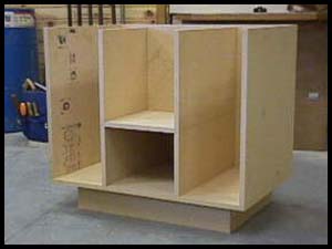
- The Carcase
The size of the tabletop for any router table shouldn't be much greater than 2' x 3' therefore the
carcase size is quite important to get right.
Proper dimensioning allows the countertop to extend past the carcase by 1 1/2" on the sides and 5" on the front
to provide easy clamping of jigs and accessories. The size shouldn't be much less than this either because of the work you can expect to perform at the router table. I've seen them larger and smaller but this size has always been my favorite.
Just like the workbench, the router table's height should be where you can stand comfortably over it while work is being performed. This is also a safety issue because being able to see exactly what is going on while using the router table should be of paramount concern to the operator.
The actual dimensions of this carcase are 20 1/2 " d. x 33
1/2" w. x 30 1/4" h. Keep in mind the carcase is just
what you see here; no face frame and no side panels.
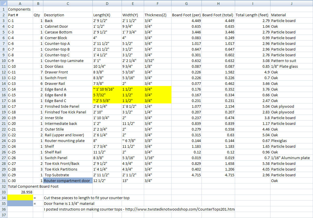
HERE is a detailed cutlist of all the
parts.
If you are a SketchUp user
then you can download the .skp file
HERE.
It was modeled using version 7
I made the toe-kick 4 3/4" high so that by the time the face frame is placed onto the
carcase, the resulting space between the bottom of the face frame and the floor will yield 3 1/2", which is standard for a toe-kick. I
opted to allow the toe-kick to surround three sides so that I could stand comfortably anywhere around it.
The drawings show it only on the front. If you decide you also want
it on the sides then you'll have to adjust the measurements accordingly. The toe-kick and the carcase are made entirely from particleboard.
The hole for the dust collection port in the router compartment is drilled at a point centered on
the intermediate shelf in front of the intermediate back. It is advisable to drill or cut this hole before you assemble the
carcase. Make this hole big enough so that the large end of the 3" PVC adapter fits tightly.
Strike your lines on the bottom and back where the partitions will sit then glue and staple (or screw or nail or whatever) the
carcase and toe-kick assembly together. I wouldn't recommend gluing the toe-kick assembly to the bottom of the
carcase because you may have to remove it at some point in the future.
The intermediate back sits on top of the intermediate shelf so that 7 1/4" lies in-between the back and the intermediate back. I designed this space in order to provide an area where the bulk of the electrical connections can be made so they can't be seen in the router cavity.
Step 2 - The Face Frame
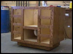
Assembly of the face frame is straightforward, however be sure that the shelf rail is 12" down on the center stiles and the drawer rails are 4 3/16" apart. If the
carcase was assembled correctly, the inside edges of the center stiles will be flush with the center partitions and the shelf rail should be flush with the shelf.
The face frame will probably get your vote as the section most likely to make you set your hair on fire. This is because of the number of pieces all needing to be glued and set into their proper places all at the same time. But, if you work on it with a plan and don't get excited, you'll adapt and overcome.
With this particular glue-up be sure to have your clamps at the ready. A biscuit joiner could be used but strength within the frame isn't necessary and
would make assembly more hectic. I used 7 clamps and glued the entire assembly together at the same time.
Set the clamped assembly aside to allow the glue to dry.
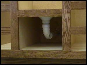
Step 3 - Dust Collection
Your first experience with any router table that is not equipped with some form of dust collection will fast convince you that a change is in order. Dust, as it is swirling around in the table gets sucked into the router, which isn't healthy for the router. Not only that, but it forces you to clean the inside on a regular basis - so why put up with it? You can add a simple pipe system, allowing your vacuum to do the job for you. I used 1 1/2" PVC pipe that adapts perfectly with My Spiffy Shop Vac™ and my central dust collection system. While your face frame is curing in the clamps, let's install the piping for the dust collection.
The plumbing is mostly 1 1/2" schedule 40 PVC but the first fitting is a 3" x
1 1/2" reducer. This fitting is important because it creates a venturi effect.
 1 - sanitary 4-way tee 1 - sanitary 4-way tee
2 - 1 1/2" sweep 90's
1 - 3" to 1 1/2" reducer
1 - 1 1/2" slip plug
5' - 1 1/2" pipe
Hopefully, the hole has been already drilled in the intermediate shelf. If not, then drill a hole to accommodate the 3" reducer. The hole should only be big enough to allow the reducer to just slide through. Next, cut a short piece of pipe so that you're able to connect one of the sweeps to the reducer then put these pieces together (do not glue them at this time). Spin the sweep around so that you can measure the distance from the bottom to the center of the sweep then transfer this measurement to the back of the
carcase and cut that hole. Be sure it is only large enough so that the bell end of the remaining sweep can pass through.
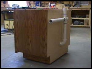
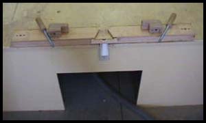
The next step is to provide piping for the suction from the fence and finally to the vacuum. In the picture (left), the sanitary 4-way tee has to be used because the turns are curved in the direction of the suction out, making it easy for debris to make the curves without getting lodged in the tee. The pipe sticking up from the tee allows a connection from the fence to help in the dust collection process.
 It would do no good to have debris remaining near the fence when it's so easy to provide for dust collection at that location, too. The tee in the system allows you to extend another piece of pipe up near the tabletop so that a hose can connect the fence into the system. It would do no good to have debris remaining near the fence when it's so easy to provide for dust collection at that location, too. The tee in the system allows you to extend another piece of pipe up near the tabletop so that a hose can connect the fence into the system.
The system should project 1 1/2" behind the back of the
carcase so that the overhang of the tabletop will not interfere with the dust collection system. The piece above the tee should be allowed to extend above the tabletop - for right now, cut it long. When all the parts are cut, assemble them dry to be sure they all fit. At this point, screw through the sides of the adapter into the shelf so that it remains in position.
By now, the face frame should be ready to remove from the clamps. Sand and finish it to your satisfaction. The face frame's dimensions are such that 3/8" will overhang the
carcase on each side. The purpose of this is to allow for a 1/4" panel to be applied to the particleboard sides thereby leaving the face frame 1/8" proud of the side panels. I used 1/4" Red Oak plywood for these panels and for the toe-kick covering. Rip these pieces to 4 5/8" and long enough to cover the three sides of the toe-kick and cut the panels to fit the sides then sand and finish. Once the finish has dried apply the face frame, side panels and toe-kick covers to the
carcase. I used brads and glue here.
Step 4 - Drawers & Doors
 The type of drawer system you use is entirely up to you. I used drawer slides from Blum but since there are so many manufacturers of these things it's really difficult to address making drawers. I made mine with simple butt joints, stapled together. They are 18" long and 1 1/16" narrower than the drawer opening in the face frame, which is in this case, 6 1/16" wide and 1" shorter in height. All the stock was ripped at the table saw using a melamine blade and cut to length at the miter saw. The bottoms are stapled on the assembled drawer parts. I used melamine but particleboard or something fancier would work just as well. The type of drawer system you use is entirely up to you. I used drawer slides from Blum but since there are so many manufacturers of these things it's really difficult to address making drawers. I made mine with simple butt joints, stapled together. They are 18" long and 1 1/16" narrower than the drawer opening in the face frame, which is in this case, 6 1/16" wide and 1" shorter in height. All the stock was ripped at the table saw using a melamine blade and cut to length at the miter saw. The bottoms are stapled on the assembled drawer parts. I used melamine but particleboard or something fancier would work just as well.
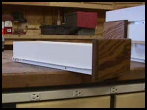
The drawer fronts (left) and the lower door of the plumbing compartment were made from Red Oak MDF while the router compartment door was made from 4/4 Red Oak and the joints mitered. A rabbet was cut on the inside edges to receive the Plexiglas panel. I then drilled 3 - 3/4" holes near the top of the Plexiglas panel to allow make-up air to enter the router compartment. These holes are important because air coming in from the top assists in drawing dust and debris down past the router and into the vacuum port.
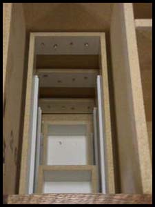 The drawers are supported by a unique method. The drawer assembly supports (left) will work in ANY cabinet and are surprisingly stout despite the cheesy appearance. The sides are 3" wide and 2 1/2" shorter than the distance from the inside back of the
carcase to the front of the face frame. The rear piece is always the same length as the actual drawer opening in the face frame. You attach the drawer glides with screws then staple together the assembly. I made a jig that works universally on every length of drawer slide. The drawers are supported by a unique method. The drawer assembly supports (left) will work in ANY cabinet and are surprisingly stout despite the cheesy appearance. The sides are 3" wide and 2 1/2" shorter than the distance from the inside back of the
carcase to the front of the face frame. The rear piece is always the same length as the actual drawer opening in the face frame. You attach the drawer glides with screws then staple together the assembly. I made a jig that works universally on every length of drawer slide.
The drawer assembly supports are best installed by working from the bottom up. You first screw the ears of the slide to the inside edges of the face frame. Then, after the drawer is in the glides, reach into the cabinet and support the rear with one hand while the other hand keeps the drawer front flat and tight to the face frame. Next, (this is where a shop helper comes in handy) staple (or nail or whatever) through the back of the
carcase into the rear section of the assembly (see photo, left), the staples (or whatever you use) should be long enough to poke through. Two staples, one at each end is placed then the drawer is checked for unhindered operation or for improper drawer front alignment. If so, the rear can be shifted left/right or up/down then the final "holding" staples can be placed.
Step 5 - Wiring
The concept of a router table is such that when you 'throw the switch' the router starts and also turns on the vacuum system. Basically what occurs is the switch sends power to an outlet where the router and vacuum are plugged into.
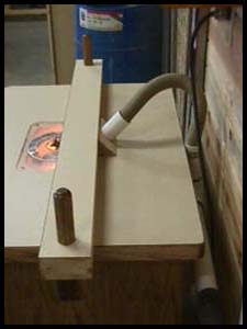
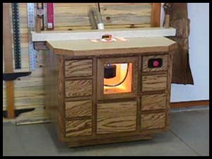
I wanted a light inside the router compartment that would either come on when the router was started or when the door was opened. So, I went to my favorite shopping mall and liberated a micro switch from some electronic gizmo and the light fixture from a discarded freezer. The light is just about the nicest feature of this router table. It not only allows you to see what you're doing when changing bits but when in use, there is surprising clarity, as you look down onto the rotating bit. I believe the best location to mount it is directly behind the router and as close to the tabletop as possible.
This part of the project was the most fun for me as it allowed me to be imaginative in keeping the wires tucked neatly away. Under normal circumstances I'd provide instructions and a photograph, but due to liability issues, I will not advise how to go about wiring your router table. If this is something you're not comfortable with then I suggest you seek the help of a friend or professional. Books on wiring are available from your local library or the WEB. I will suggest that you NOT use a standard household light switch. These switches are too easy to toggle on and the amps involved will eventually be a fire hazard. Instead, use a panic type switch where you have to pull it out to activate it but merely hit the paddle to turn it off. The one I used was manufactured by Cutler-Hammer
- look in the Yellow Pages for an electrical supplier in your area.
If you decide to incorporate a light in your table then your switch will need two modules; one each for the router and light.
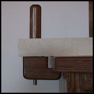
Step 6 - The Fence and Table Top
 The fence is another one of those areas that can be classified as "user defined." The router table that Uncle Norm made some time ago had quite the elaborate fence system but the greatest problem I had with it was how it attached to the top. I didn't like where slots were cut into the top that allowed the fence to slide perpendicular to the bit. To my thinking, a slot in the top weakens it, so I came up with a different way to hold the fence tight to the top. The picture to the left shows the underside of the fence and that each end has three holes drilled into it. The two outer holes accept the guide pins of the clamp block. As the knob is tightened the clamp block is pulled up on the guide pins. These pins are 5/16" steel rods that are glued in the blocks. The fence is another one of those areas that can be classified as "user defined." The router table that Uncle Norm made some time ago had quite the elaborate fence system but the greatest problem I had with it was how it attached to the top. I didn't like where slots were cut into the top that allowed the fence to slide perpendicular to the bit. To my thinking, a slot in the top weakens it, so I came up with a different way to hold the fence tight to the top. The picture to the left shows the underside of the fence and that each end has three holes drilled into it. The two outer holes accept the guide pins of the clamp block. As the knob is tightened the clamp block is pulled up on the guide pins. These pins are 5/16" steel rods that are glued in the blocks.
An
AutoCad drawing of my fence is available
HERE.
A detailed page showing how it's made is
HERE.
 The through rod is 1/2" all thread and a nut is recessed into the bottom of the clamp block. The handle has about 1 1/2" of the all thread passing into it with a hole drilled horizontally through the handle and all thread. A pin is then inserted into the hole and glued in place - this keeps the handle from spinning on the all thread. The through rod is 1/2" all thread and a nut is recessed into the bottom of the clamp block. The handle has about 1 1/2" of the all thread passing into it with a hole drilled horizontally through the handle and all thread. A pin is then inserted into the hole and glued in place - this keeps the handle from spinning on the all thread.
The "vee" on the underside of the fence acts as a venturi for the dust collecting port. I made my whole fence a single piece because I didn't see the need to have a split fence.
I made the top so that 4 3/4" protrudes in front of the face frame and 1 1/2" over the remaining three sides and the front two corners were clipped 45 degrees (see the photo at the beginning of this article). So, the tabletop's final dimensions are 36 3/4 " x 28". Particleboard was used for the substrate and plastic laminate was used for the covering on the top and fence. The edges are 4/4 Red Oak.
I don't believe a miter gauge slot needs to be in a router table so that's why you won't find one on mine.
Step 7 - Bits & Pieces
The MTO (material take-off):
2 sheets of 3/4" particleboard (carcase and tabletop)
1 sheet of 1/2" particleboard (carcase back and drawer components)
1" x 8" x 8' Red Oak (or whatever)
1 piece Plexiglas
4 hinges
1 light socket
1 micro switch
wire
1 plumbing kit as described above
7 sets of drawer slides
36" x 48' plastic laminate (tabletop and fence)
panic-type switch
The router table will be perfectly content sitting on its toe-kick, however if you made it from particleboard then you'll have to take care when moving it around. Particleboard isn't too strong on the edge and will be susceptible to chipping out when it's moved across the floor. I overcame that obstacle, once again, by going shopping at my favorite mall. I liberated some steel supports that are commonly found on commercial kitchen appliances (you know the ones - they're about 5" long, have a height adjustment and have a bolt stud at the other end that screws on and they're tapered?). I welded a nut onto a steel plate and screwed it onto bottom of the
carcase then attached the legs. After they were attached, the toe-kick ended up being elevated about 1/2" off the floor, providing a nice shadow line and hiding the existence of the legs.
The drawer fronts and doors are 1/2" overlay. This means that they are 1" wider and taller than the actual drawer or door opening in the face frame.
I used the European type hinges by Blum.. They are 110 degree opening and are the screw type, not the dowel type. If you use these you'll need a 35MM hinge boring bit (available where you buy the hinges) and the mounting plates (be sure you order them for 1/2" overlay). I really like these hinges because they are hidden, they operate extremely well and are reasonably priced when you buy them in bulk ($1.53 each).
I used 3/8" acrylic for the plate that my Porter Cable, fixed based, 3-1/2HP router is mounted to. The proper location of this plate in your top is critical in that the center of the plate must be in the center of the router compartment and the center of the router mounted to the center of the acrylic plate. I suggest you temporarily clamp the top to the
carcase and use a plumb bob to locate the location of the top in relation to the center of the dust collection port in the router compartment.
One thing I didn't touch on was the actual router bit holders. Because there are seven drawers in this table, there is plenty of room for all sorts of router-related accessories and bits. Again, I feel the method of how you display the bits in each drawer to be user defined as this will give you something to putz around with. If you decide to build this cabinet and feel you've come up with something snazzy, I'd like to hear from you. If you have any questions just Email ME.
I trust you'll enjoy building your new router table as much as you'll enjoy using it. I had a jolly nice time putzing around with mine - the shopping trips to the landfill aside - because I was able to incorporate ideas I've been thinking of since I built my previous table
in 1995.
I'd really like to hear from you if you decide to build this table or a version thereof . If you do, feel free to send ME a written description and some pics and I'll post it HERE where our woodworking colleagues can see how your table looks and perhaps inspire them to build their own. |


